Showing posts with label Windows. Show all posts

Monday, 7 April 2014

Lesson 8: Limiting the Scale tool, and other attributes

This week, a break from creating dynamic components with a look at the other attributes in the Component Attributes window. We have already seen many of them and most are self-explanatory but let's look at some of the others.

The group titled "Component Info" are all to do with what appears in the Component Options window. The position of the various attributes are shown below. You can also see a piece of italic text in the description and this is to show that you can use HTML codes in any of these areas. Only certain codes are available but they can make your text look more interesting and you can add links to your webpage, for instance.


Available HTML codes
    <a> anchor
    <b> bold
    <i> italic
    <u> underline
    <strong> bold
    <em> italic
    <p> paragraph
    <br> line break
    <ol> ordered list
    <ul> unordered lis
    <li> list item
    <font> font size, colour, etc

The "Form Design" group have similar uses. "ImageURL" allows you to replace the default thumbnail with your own image. The "DialogWidth" and "DialogHeight" determine the size of the Component Options window. (If you are working on a large screen, don't make the "DialogHeight" too large – remember other people will have smaller windows.)

The "Hidden" attribute simply hides or shows a subcomponent. This could be useful where, for example, you have a vehicle with different designs – a lorry that could be flat bed or enclosed. I also used it in a restaurant dining table/ chair set so that you could have variable options – one chair, two chairs opposite, two chairs side-by-side.

The final attribute "ScaleTool" is often used with dynamic components to disable or limit the use of the Scale tool with your component. As an example, imagine you have created a ladder that adds extra rungs as you lengthen it (increase the LenX). It would be all right for the Scale tool to be used to make the ladder longer but not to change the other dimensions (LenY or LenZ). That would distort the rungs and supports. With the ScaleTool attribute, you can disable some or all of the ways the Scale tool can be used.

To do so, double-click the "ScaleTool" attribute or click the menu-arrow icon to the right. The screen below appears.
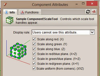

As you click on the checkboxes, you can see the handles appear and disappear meaning that the Scale tool cannot be used in that way. The easiest way to understand is to deselect some of the checkboxes, click apply, and then try to scale your component with the Scale tool. The setting below shows how the checkbox combination is mirrored when using the Scale tool.

Tuesday, 11 March 2014

Lesson 3: Entering formulas

In the last lesson, we looked at entering values into the Attributes window but what makes a component dynamic is formulas – the ability for some attributes to change depending on others.

Start by creating a cube 10cm on each side (you can use inches if you want – units are not important) and making it into a component. Then open the Component Attributes window, select the cube and add the size attributes (LenX, LenY and LenZ). They should all be showing "10". (If they aren't, just enter 10 into the incorrect attribute and press return).

The first thing we are going to do is fix the height (LenZ) so that it remains fixed at 10 whatever else we do to the cube, such as scaling. This is a common task in dynamic components. All we have to do is type "=10" into the LenZ attribute box (not the quote marks, just equals and ten).

Note: if you simply add the = in front of the existing text, you might see this appear:

This means that SketchUp doesn't recognise what you enter. You have to remove the "cm" so the value you enter is "=10". The "cm" will appear when you press return but that is simply SketchUp showing you the units. You don't enter them yourself.

Now take the scaling tool and try changing the dimensions of the cube. If everything is correct, you should see the height change but snap back to 10cm when you release the mouse. The LenZ attribute is now fixed.

TIP Before we go on, a tip. You can either see the computed values or the formulas in the attributes boxes. To toggle between the two, click the "=ƒx" button at the top right of the  Attribute window.

Now we want to link the width (LenY) of the cube to the length (LenX). So delete the contents of the LenY attribute and enter "=LenX/3" and return (again not including the quote marks). What this means is that LenY is set equal to LenX divided by 3. The width of the cube should automatically change to 3.333 cm as soon as you pressed return.
Now try scaling the cube again and you should see the width automatically change to one-third of the length.

If you haven't done so, try scaling just the width using the scaling point below.


You should notice that the cube* remains the same size but simply moves its position. What happened? Well, we have determined that the width is calculated according to the length. We have changed the width but not the length so SketchUp calculates the new width dependant on the length which hasn't changed. The scale tool cannot override the formulas.

You could try switching the length and width around by deleting the LenY formula so that it just shows the value (in grey) and entering "=LenY*3" in the LenX box. Now you see that the scaling tool can change the length but not the width.

TIP When you are entering formulas, you can enter the attribute directly rather than type it by clicking on the attribute name in the window (see below).


What happens if you want to connect the width to the length and the length to the width? If you have the two formulas in both boxes at the same time, you will get the red # coming up to show that SketchUp cannot accept it. It's a circular reference. The LenX value is based on LenY and the LenY is based on LenX. SketchUp, just like a spreadsheet, cannot complete the calculations and will throw a wobbly.

To finish off, try entering various formulas using the position attributes (X, Y and Z). If the formula in position X is "=Y*2", then moving the cube along the X axis will automatically move it to a new Y position. Try entering different formulas in different boxes until you are quite happy with how they work.

* I know it's probably not strictly a cube now but a box, but we won't confuse things by changing the name.

Monday, 10 March 2014

Lesson 2: Entering values

Before you start creating dynamic components, you need to fully understand the component attributes window. So create a simple 3D object such as a cube or cylinder and turn it into a component, giving it a name when you do so (such as "My DC cube"). Then open the component attributes window and make sure your component is selected.

You’ll see in the window a little bar with the same name that you gave the component. This represents the component itself. If it was made up of groups or sub-components, they would be listed beneath this. Beneath the name, you will see "Add attribute".


The attributes in question are all the things which define your component: the position (X, Y, and Z co-ordinates), the size (LenX, LenY and LenZ), the angle or rotation (RotX, RotY and RotY), its material, whether it is visible or hidden, etc.

You can show an individual attribute by clicking "Add attribute" or the plus sign beside it and choosing one of the pop-up list. You can see that they are in groups and you can show all of a group by clicking on the title. If you hover on "Position", it changes to "Position (add all)" - click the title and all three position attributes are added.

You will see that some attributes, such as position and length, already have values in grey. That is because they already exist (any object must have a position, length and rotation) while others such "Name" are blank and can be filled in by you. (The attributes window is basically a spreadsheet and, like that, can contain values or formulas, but we shall look at that later. For the moment, just concentrate on values.)

You can delete an attribute by clicking on it and then clicking the minus sign beside it. Attributes that have existing grey values retain them if you delete them (an object cannot have no length after all) but those that you have written into will lose them.

For the moment, just add all the position, length and rotation attributes. You should see something like this (the value will obviously be different for your component).


Now double-click in the X field (where it says 0 cm in the picture, not the red "X"). Delete the value inside and enter something else such as "20" and press the return key. You should see your component move. to the new X position. Try entering different values in the other fields and see what they do.

Now try moving, scaling or rotating the component itself with the usual tools. See how the attribute values change as you change the object. Finally show the "Material" attribute which will probably be blank. Then apply a material to the component and see how its name appears in the field.

For the rest of this lesson, familiarise yourself with these attributes and how they relate to the component. A clear understanding of this is vital to creating dynamic components.

Sunday, 9 March 2014

Lesson 1: Introduction to the DC tools and windows

We start then with an overview of the way you interact and create dynamic components (DCs)

(Remember that you must have the Pro version of SketchUp to create DCs although you can interact with existing ones with the free version).

There are four tools/windows used with DCs, three specifically and one, the scale tool, which can work differently with some DCs. These are shown below. (The dynamic component toolbar is opened from the View > Toolbars > Dynamic Components menu).

The menu and toolbar to access DC tools/windows
The only specifically-DC tool is the Interact tool (the pointing hand) which (depending on the component) will do certain things when clicked on the DC (such as open and close doors). The next button in the toolbar opens the "Component Options" windows which, again depending on the component, allows you to choose or enter various things (such as the width of a door). The third button opens the "Component Attributes" window which is what you use to actually turn a plain component into a dynamic one. The fourth button shown is the familiar Scale tool which can operate differently with some DCs.

As seen above, the "Component Options" and "Component Attributes" can also be opened from the Window menu and the right-click context menu.

Using the tools and windows

To see how the tools and windows work, go to the 3D Warehouse and download the simple DC figure called "Sang" (Direct link). Do not open directly (or it won't work) but create a new, empty SketchUp document and import it.

Now click on the Interact tool (the pointing hand) and hover it around the figure. You should see the cursor change over different areas as shown below. If you click on any active area, you should see the figure's colours change.


Now open the Component Options window while the Sang figure is selected. You should see something like this:


As you can see, this component gives you the option of changing the colours by entering the choice in the Component Options window (and clicking Apply). Some DCs can be changed via the Interact tool, some by the Options window, and some by both.

Finally open the Component Attributes window and you should see this:

This is where the formulas that define the "dynamic" part of the dynamic component are entered and we actually create the DC. This is also where it can get complicated so it is an area that needs to be taken slowly. For now, you should download a few more dynamic components and play around with them.

A sample of DCs is installed with SketchUp (in the Dynamic Components library in the Components window). You can see they are DCs by the little green icon beside the thumbnail (see below).

If you go to the 3D Warehouse, click on the little cogs in the search box at the top of the page. This takes you to the advanced search where there is a checkbox for "Show only dynamic models".